How to determine your tool shrinkage?
Plastics expand when heated and shrink when cooled. Typically semi-crystalline materials will shrink more than amorphous materials.
We have the pack and hold phase to add additional material into the mold to combat these shrinkages. We can also apply shrink factors to the tool cavity, essentially making the tool cavity larger so when these materials shrink, we get our desired part dimensions.
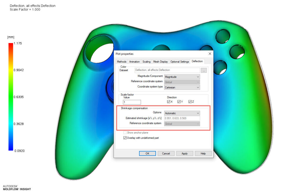
So where do we get these mythical shrink rates? Sometimes the material’s technical data sheets (TDS) may contain some shrink information while other times we may rely on the awesome tool makers – both are good options. If you run a Warp analysis in Moldflow – you can also get shrinkages that are specific to your CAD model, your material, your runner, and cooling design. If you go to the Deflection All Effect – Plot Properties – Shrink Compensation, you have options. Automatic (Moldflow picks the best shrinkages for X, Y, and Z), Isotropic (you select a single value), or Anisotropic (you select the X, Y, and Z values).
This feature is unfortunately underutilized in my experience. I would encourage you to have your runner modeled, quality material data, and ideally, your cooling modeled as well.
I would use these values to compare to the material TDS or your tool shop’s recommendation. Hopefully, these 3 suggestions align and you can select your shrink rates.
How do you determine your tool shrinkage?


